Product Description
HOW DO OUR PADDLE WHEEL FLOWMETERS WORK?
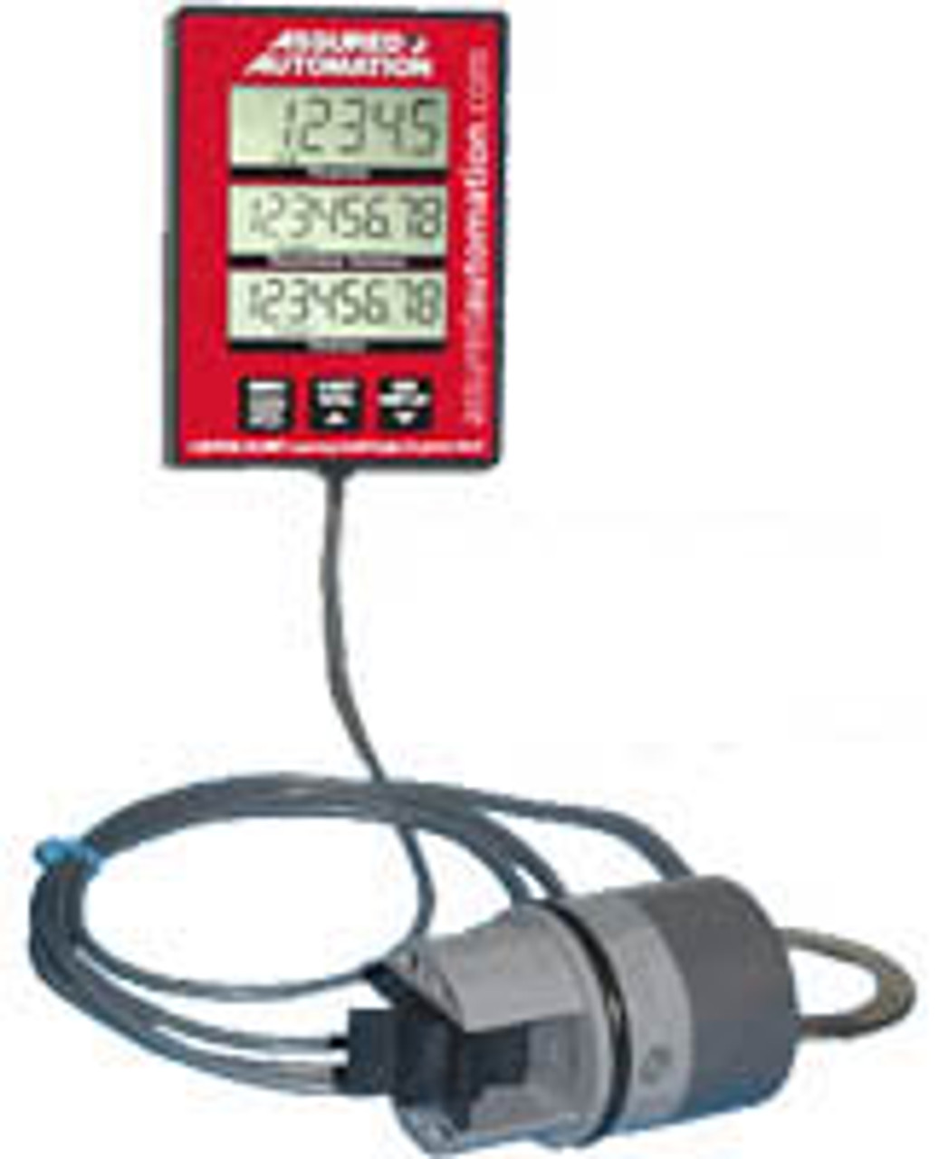
Our paddle wheel flow meters consist of three major components:
- Paddle wheel sensor
- Sensor to pipe mounting adapter - "saddle style" insertion or "pipe section"
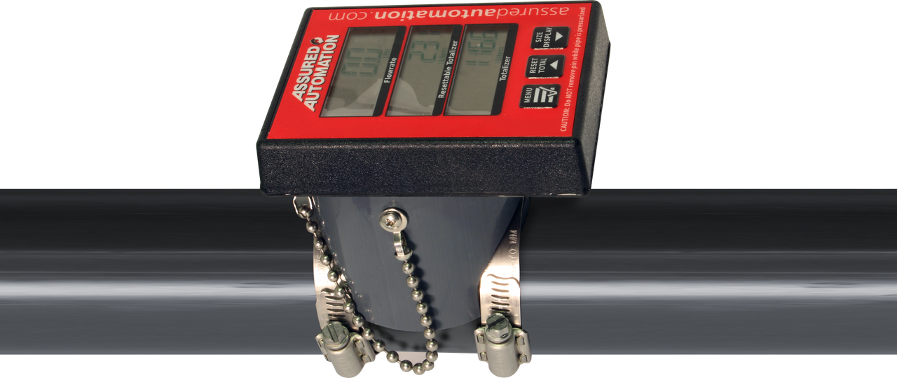
- Local or remote electronics with digital display
Paddle Wheel Sensor
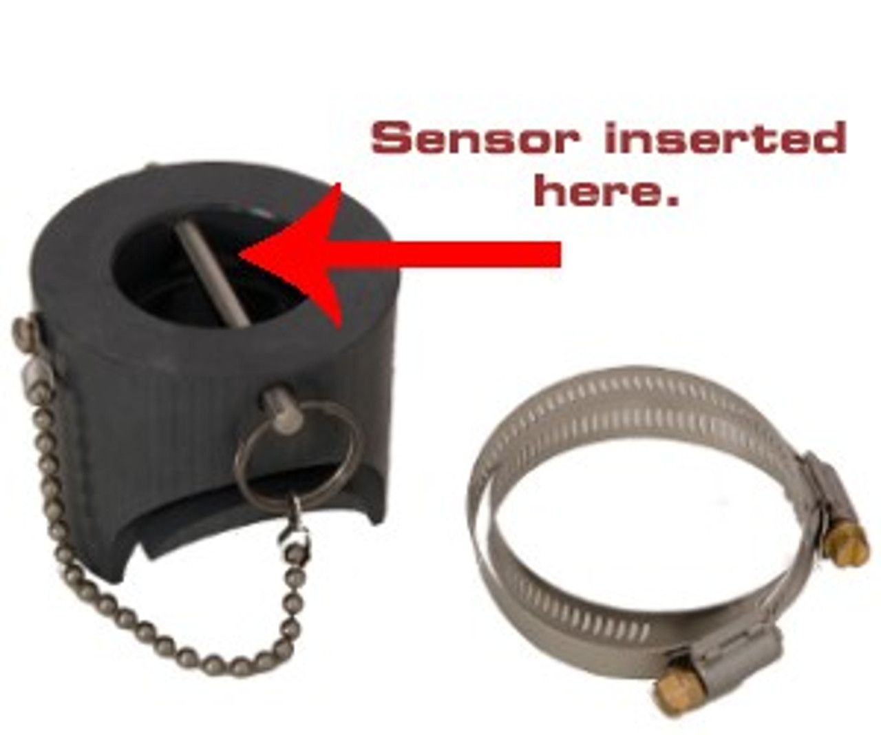
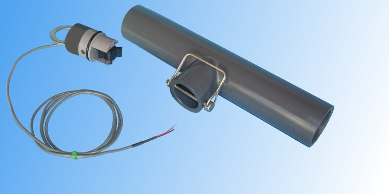
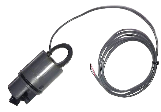
The Paddle wheel sensors are all the same. The electronics are programmed and calibrated to make them work with the different pipe diameters and schedules. The sensors used for WM-PT paddle wheel water meters can be mounted right on the sensor, or remotely with a wired connection. The paddle wheel sensor is inserted into the adapter, held in place by a pin, and sealed with an o-ring. Remote, "wall mount" models are connected to the digital display with a 15 ft wire (call for longer lengths).
Liquid flowing in the pipe causes the paddle wheel to spin at a rate linearly proportional to the flow rate. Magnets, contained in the paddle, rotate past a switch; pulses from the switch are processed by the microprocessor and then displayed as a flow rate on the remote LCD display. The WM-PT is used effectively as a pool water meter, and for septic effluent, and gray water applications. In addition, utilizing the remote mount display it makes the perfect solution for meters that are installed in a pit.
These sensors are easily removed by removing the pin and pulling the sensor out while the system is NOT pressurized. A temporary replacement plug is available to replace the sensor in case the line must be used while the sensor is out.
|
Sensor and Wire |
Replacement Plug | |
|
|
|
Sensor Mounting Adapters
CHOOSING THE CORRECT ADAPTER
The flow rate must be within the recommended range for the flowmeter to function properly. Inadequate flow velocity in large pipes is the number one reason flow meters don't operate as expected. An adequate flow not only reliably spins the paddle, it also washes silt and air bubbles out of the pipe. If the flow rate is at or below the minimum recommended rate, neck down to a smaller diameter pipe.
For pipe sizes 2" and smaller, most people purchase the pipe section adapter as they are easier to install. However, with 3" and larger pipes, splicing in a section of pipe becomes more difficult and the insertion mounted adapters are desirable. The six and eight inches meters are only offered in the insertion mounted style.
|
|
 |
|
|
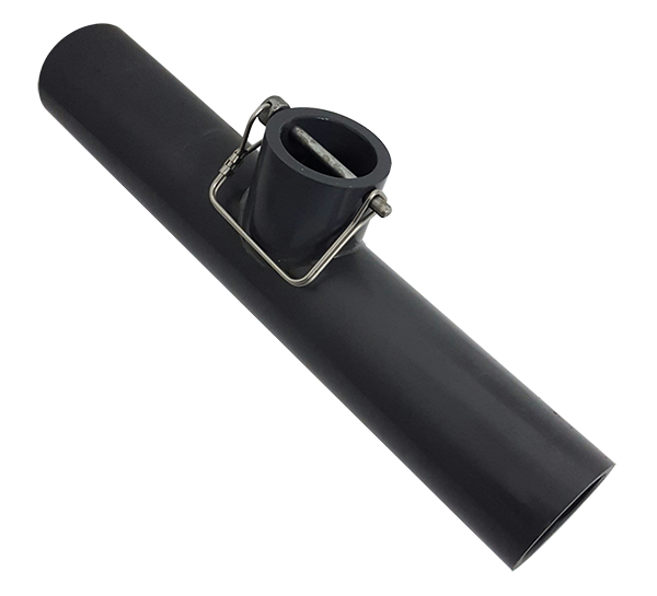
Pipe Section Adapter - (1/2" to 4" pipes) The fitting for the meter is solvent welded to a 13" section of pipe. Pipes sizes range from 1/2" to 4". For 6" and 8" pipes, you must use the saddle style insertion adapter. In the 1/2", 3/4" and 1" models the adapters are only offered in schedule 80 pipe sections. Schedule 40 fittings will glue directly to schedule 80 pipe, since the pipes have the same outside diameter. |
Insertion Adapter - (1 1/2" to 8" pipes) Saddle style fittings are designed to mount directly on your existing pipe. If you are ordering an insertion style adapter for your existing plumbing, it must be for your exact pipe. The adapters are machined to fit the outer diameter of the pipe and also compensate for pipe wall thickness differences. Therefore, if you mount an adapter for a schedule 40 pipe on a schedule 80 pipe, the meter will produce very inaccurate results. We can custom machine adapters as long as the pipe has a smooth outer surface. |
Electronics with Digital Display
The digital display shows flow Rate, Resettable Total, and Lifetime Total in Gallons, Liters, or Cubic Feet. It can be field calibrated to adjust for inaccuracy.
INSTALLATION NOTES
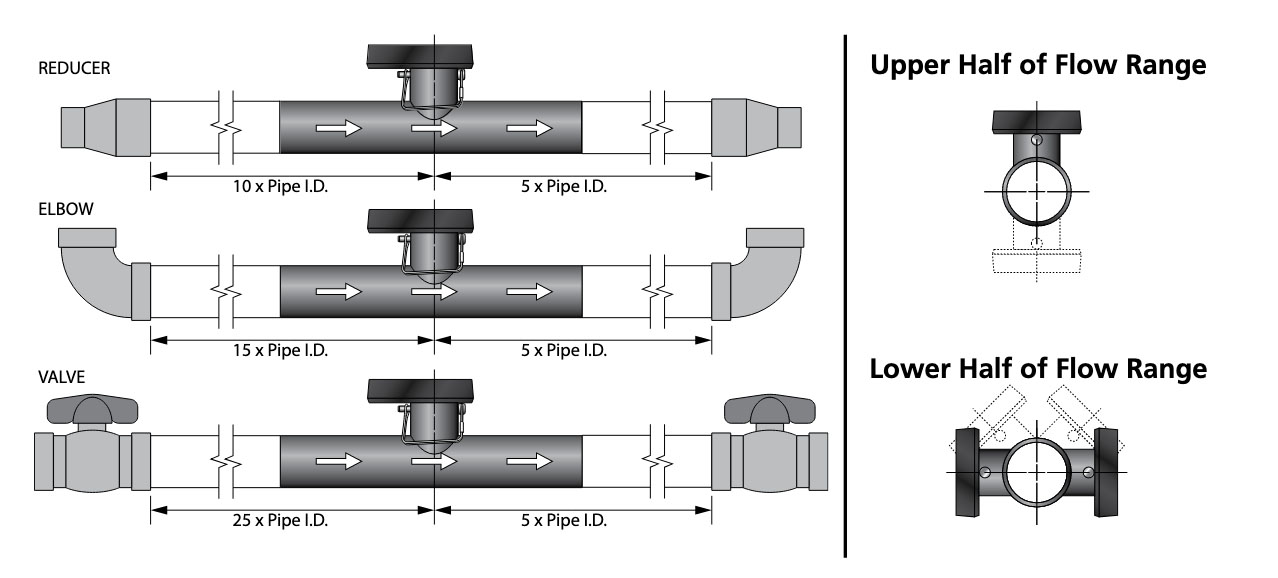
The accuracy is based on steady, undisturbed flow with a fully developed laminar flow. Swirling and other disruptions in the flow will affect the meter’s accuracy. Uniform developed flow is produced in straight runs of pipe.
The meter must be installed in a straight length of pipe with at least 10 pipe diameters upstream of the meter. The length of pipe downstream must be at least 5 pipe diameters. Major flow obstructions, such as gate valves, pumps and multiple elbows will require longer straight runs of pipe before the meter.
Back pressure is needed on downward flows to assure the pipe remains full of water. IT MUST BE A COMPLETELY FULL PIPE OF WATER WHEN MEASURING TO BE ACCURATE!
Schedule 40 and 80 Explanation:
"Schedule" refers to the thickness of the pipe wall and, therefore, how much pressure it will hold. In most aquaculture applications, Schedule 40 is used.
SCHEDULE 40: From 1/2" to 2", it is rated at no less than 140 psi at 73°F.
SCHEDULE 80: Up to 2", it is rated at no less than 200 psi at 73°F.
Documentation:
